Reading Alloy Phase Diagrams
The phase diagram of an alloy made of components A and B for all combinations of T and X B defines the A-B system. They are also useful in solving problems that arise in their performance in commercial applications thus improving product predictability.
 Cct Diagram Steel Materials Engineering Material Science Mechanical Engineering
30 reviewed data from 1906 through 1966 to verify results for a more detailed phase diagram.

Reading alloy phase diagrams. Introduction to Alloy Phase Diagrams Hugh Baker Editor ALLOY PHASE DIAGRAMS are useful to metallurgists materials engineers and materials scientists in four major areas. Introduction to Materials Science Chapter 9 Phase Diagrams 11 Isomorphous system - complete solid solubility of the two. The diagram is presented in the picture.
A hypothetical ternary phase space diagram made up of metals. Volume 3 provides a complete explanation of phase diagrams and their significance and covers solid solutions. This diagram contains two binary eutectics on the two visible faces of the diagram and a third binary eutectic between ele-ments.
From Figure 918 the composition of an alloy at this temperature is about 17 wt Pb. Binary systems have two components ternary systems three and so on. The volume includes 1083 binary systems 1095 binary diagrams 115 ternary systems and 406 ternary diagrams.
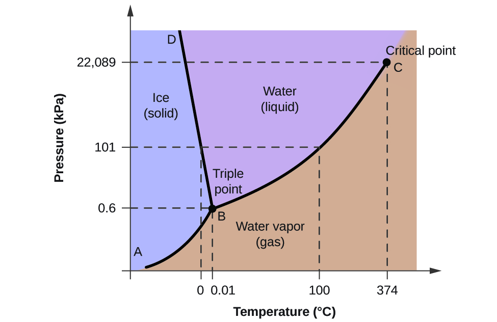
Phase diagrams for binary systems ternary phase diagram of Ni-Cr-Fe. Phase diagrams can be used to predict the phase changes that have occurred in an alloy that has been exposed to a particular heat treatment process. The phase diagram shows in pressuretemperature space the lines of equilibrium or phase boundaries between the three phases of solid liquid and gas.
Ternary systems therefore are often represented by views of the binary diagrams. Because it is difficult to use. Components use the.
Only B crystallizes because we are on the MeltB liquidus line. A binary phase diagram is a plot of temperature versus composition. Is shown in Fig.
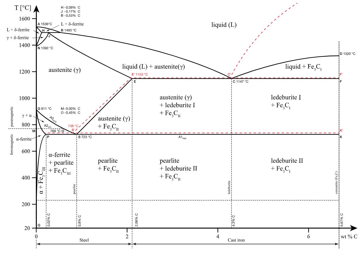
Iron-carbon phase diagram describes the iron-carbon system of alloys containing up to 667 of carbon discloses the phases compositions and their transformations occurring with the alloys during their cooling or heating. B At 400C the solubility limit of the α phase. The curves on the phase diagram show the points where the free energy and other derived properties becomes non-analytic.
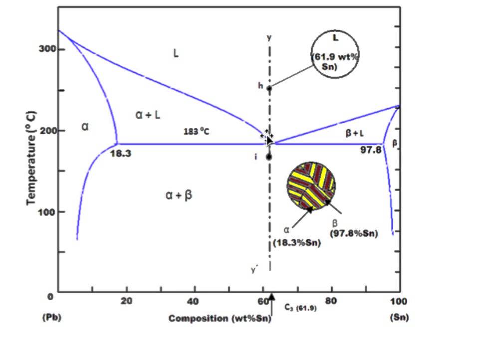
Alloy phase diagrams are useful for the development fabrication design and control of heat treatment procedures that will produce the required mechanical physical and chemical properties of new alloys. As axes are called phase diagrams. A eutectic system j uː ˈ t ɛ k t ɪ k yoo-TEK-tik from the Greek εύ eu well and τήξις tēxis melting is a homogeneous mixture of substances that melts or solidifies at a single temperature that is lower than the melting point of any of the constituents.
Phase diagrams are graphical representations of the phases present in a particular alloy being held at a particular temperature. Alloy phase diagrams are useful to metallurgists materials engineers and materials scientists in four major areas. Carbon content 667 corresponds to the fixed c omposition of the iron carbide Fe3C.
Their derivatives with respect to the coordinates temperature and pressure in this example change discontinuously abruptly. A B and. While three-dimensional projections can be helpful in understanding the relationships in the diagram reading values from them is difficult.
192 Phase DiagramsUnderstanding the Basics. Numbers on phase diagram correspond with numbers below 1. For diagrams where there is a major.
Thus the phase diagrams presented here are for a constant pressure of one. 31 reviewed the data for the Bulletin of Alloy Phase Diagrams. In 1968 Moh et al.
Cool melt to liquidus line along red arrow. Hidden on the back of the plot. For normal diagrams where interested in all.
An example of a phase diagram for a ternary alloy is shown for a fixed T and P below. External pressure is also a parameter that influences the phase structure. This temperature is known as the eutectic temperature and is the lowest possible melting temperature over all of.
This video used the eutectic phase diagram to define terminology and phase diagram calculation. The phase diagram for the full and 4575 sulfur fraction is shown in Fig. You read along the y-axis to read off the temperature.
So I like to think of the phase diagram as depicting a composition-temperature space. Only B crystals form at about 1380 o B is immiscible with A. Binary phase diagrams are the most commonly used phase diagrams in alloy designing.
However in practicality pressure remains virtually constant in most applications. Therefore any single point on the phase diagram represents a specific alloy composition at a specific temperature. A phase diagram or equilibrium diagram is a diagram with T and composition as axes showing the equilibrium constitution.
This video is the first part in a series about phase diagrams. The phase diagram of an alloy made of components A and B for all combinations of T and WB or XB defines the A-B system. 1 development of new alloys for specific applications 2 fabrica- tion of these alloys into useful configurations 3.
Most recently in 1986 Sharma et al. No A can crystallize until the eutectic is reached. Isomorphous eutectic peritectic and monotectic alloy systems.
You read along to the x-axis and read off the composition. Therefore the mass of Pb in the alloy is just 01775 kg 13 kg. A phase diagram or equilibrium diagram is a diagram with T and composition as axes showing the equilibrium constitution.
Fe in Fe-C-Cr use a. Lead in 75 kg of the solid α phase at 300C just below the solubility limit. According to the MgAg binary phase diagram the maximum equilibrium solid solubility of Ag in Mg is 15 wt at the eutectic temperature of 472 C and it falls to approximately 2 wt at room temperature and the intermetallic phase at the Mg-rich side of the phase diagram is Mg 3 Ag space group P6 3 mmc a 0488 nm c 0779 nm.
Binary systems have two components ternary systems three and so on. Assume a melt comp- osition of 70 B and 30 A.
Phase Diagram Industrial Metallurgists
 2 Component Phase Diagrams
 Fe Fe3c Phase Diagram Powerpoint Design Templates Education Poster Mechanical Engineering
 Equilibrium Phase Diagram An Overview Sciencedirect Topics
 Binary Alloy Phase Diagram An Overview Sciencedirect Topics
 Iron Carbon Equilibrium Phase Diagram Diagram Materials Engineering Engineering
 Phase Diagram Eutectic Youtube

 The Iron Carbon Phase Diagram
 2 Component Phase Diagrams
 Asm Alloy Phase Diagrams Database Diagram Problem Solving Intro
 6 1 2 Reading Phase Diagrams Single Phases And Boundaries
 Iron Carbon Phase Diagram Mechanical Materials Engineering Material Science Diagram
 2 Component Phase Diagrams
 Iron Carbon Phase Diagram Explained With Graphs
 Introduction To Materials Science Chapter 9 Phase Diagrams University Of Virginia Dept Materials Science And Engineering Material Science Materials Science
 Phase Diagram Industrial Metallurgists
 The Iron Carbon Phase Diagram
 10 4 Phase Diagrams Chemistry